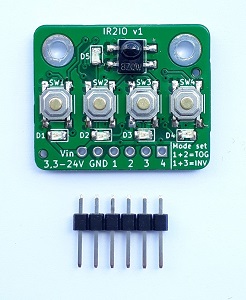
IR2IO

What is IR2IO?
It's a very easy to use 4-channel switch, controllable by any infrared remote control.
You don't need to know anything about the protocol or frequency of your remote control - the IR2IO board works with any common IR-remote control.
This is the easiest way to control your hardware by an infrared remote control.
Implementing an infrared protocol on your controller project is not so easy (you have to know some information about your remote control like frequency and type of protocol and finally you have to find a library for this which runs on your microcontroller). Most projects only need to react on some few specific buttons of your remote control - save your time and nerves and concentrate on the main parts of your project. You can now control your hardware with any IR-remote control in just a few seconds.
To cover a wide range of use cases - the IR2IO has a very large input voltage range: Any supply voltage from 3,3 V to 24 V can be used.
How does it work?
The IR2IO board has a broadband IR-Receiver. It works with all infrared signals with a base frequency between 20kHz and 60kHz. This covers all common used infrared frequencies used in IR-remote controls.
To use a button on your IR-remote to control one of the 4 outputs of the IR2IO, just press and hold the output corresponding button on the IR2IO board and then press the button on your remote control which you like to connect with this output. Thats all! Now the output is connected with this button on your remote control - anytime you press the button on your remote - the output activates as long as you press and hold the button.
Configurable
IR2IO supports three modes:
- Normal mode: This is the default mode - the output activates as long as you press the button on your remote control.
- Inverting mode: The outputs are switching to ground. This is the best way to switch loads like relais. But if you measure the voltage at the output - you will measure a high level if the switch is inactive and a low level when the switch is active. If you want, you can change this by activating the invert-mode. This is needed if you want connect directly e.g. a motorcontroller which needs high-levels.
- Toggle mode: The output will stay active even after releasing the button on your remote control. Only when you press the button a second time, the output will get inactive. With this mode it is possible to switch things on and off.
Technical Data
| Parameter | Value |
|---|---|
| supply voltage | 3,3 V* - 24 V |
| Quiescent current @5V (all outputs off) | 265 µA |
| Max current @5V (all Outputs on) | 18,8 mA |
| Switching Output current | 80 mA |
| Pull Up Resistor | 10 kOhm |
| IR-frequency | 20 kHz - 60 kHz |
| Number of outputs | 4 |
| Board Dimensions | 23 x 28 mm |
Downloads
manual schematic 3D Model - STEP File